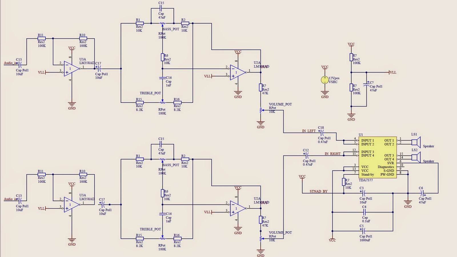
Electronics TDA7377 audio amplifier with baxandall tone control
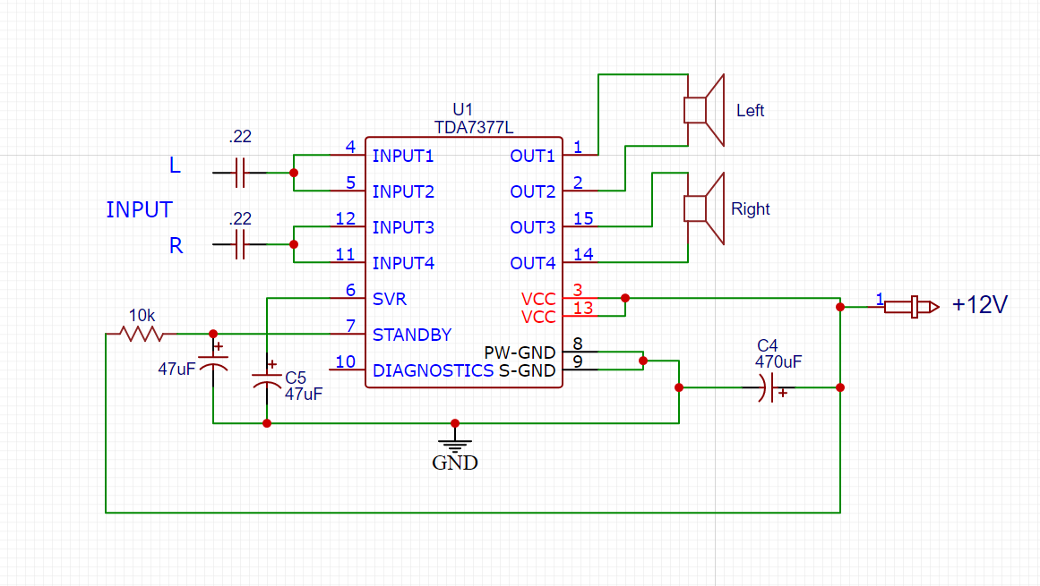
Pin configuration TDA7377 Features Dimensions: 60mm x 56mm x 50mm Output Power: 35W + 35W Power Supply: DC 9-15V / 50-100W Channel Type: 2.0 Stereo Response Frequency: 20Hz - 20kHz Compatible Speakers: 4-8 Ohm, 20-120W, 3''-10'' bookshelf speakers, floor speakers High Output Power @ VCC=14.4V, f=1kHz, RL=4Ω: - 2 x 35W Max. - 2 x 20W @ 10% THD

TDA7377A Datasheets Audio ICs Amplifier IC 2Channel (Stereo) or 4
5398 35W W Audio Amplifiers 15 pins The TDA7377 is a new technology class AB car radio amplifier able to work either in DUAL BRIDGE or QUAD SINGLE ENDED configuration. This article is going to explain datasheet pdf, circuit, pinout, power, and other details about the TDA7377 amplifier. TDA7377 stereo amplifier board test and review Catalog
TDA7377 IC Using Stereo Amplifier (30w+30w) TechSaw
This Power Amplifier using or based on IC TDA7377, that the TDA7377 IC has 4 channel input and 4 channel output. For using 2.1 Power Amplifier on two channel is bridge to one output so the output is 3 channel , one channel using for bass or subwoofer speaker. And the other 2 channel is using for mid and treble speaker. see circuit diagram below
Tda7377 Amplifier Circuit Diagram Pdf
Hi Friends, Today In This Video I Have Shown 12v Super Bass Stereo Amplifier Circuit With TDA7377 IC (30w+30w) | Low ComponentsCircuit Diagram : https://tech.

TDA7377 Amplifier Circuit (12V Stereo 30W +30W) A 2x30W amp circuit
The Integrated Circuit (IC) TDA7377 is a quad amplifier IC i.e. it has four inputs and outputs channels with each channel 15W peak power output. However, this design uses bridges of two channels to umake it a stereo amplifier, thus (30X2 = 60W) peak RMS.
TDA7377 2.1 Amplifier Circuit Diagram With PCB Xtronic
The TDA7377 is a cutting-edge class AB car radio amplifier that can operate in either DUAL BRIDGE or QUAD SINGLE ENDED configuration. Its unique fully complementary output stage and internally fixed gain ensure outstanding power performance while minimizing component count. The built-in clip detector simplifies gain compression operations.

TDA7377 2.1 Amplifier Circuit Diagram With PCB Xtronic
#TDA7377#pcb#Audio_Amplifier Follow Mehttps://www.facebook.com/Easyoneehttps://twitter.com/Eaasyonehttps://www.instagram.com/easyyone

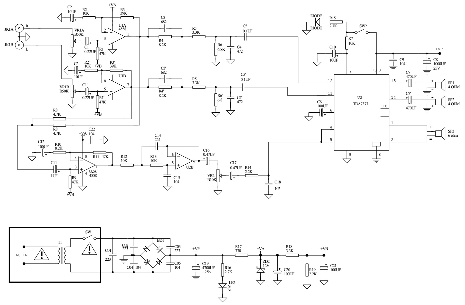
Tda7377 2.1 30 Watts Power Amplifier Schematic
The UTC TDA7377 is a class AB car radio amplifier for car radio, it can work either in dual bridge or quad single ended configuration. The exclusive fully complementary structure of the output stage and the internally fixed gain guarantees the highest possible power performances with few external components.
Circuit power audio amplifier with TDA7377 2.1 Xtronic
A friend I made for 2x30W amp circuit to say the least, this work had to take care: D tda7377 was the best choice integrated single-source supply is working with 14 volt 2 × 20 watts of power can give max supply voltage of 18 volts DC passive elements very least three capacitors first resistance 🙂 Sprint Free to View and Print output was prepare.
TDA7377 2.1 Amplifier Circuit Diagram With PCB Xtronic
It is a 2 * 30 W dual/quad power amplifier which can be used for card and radio, The TDA7377 is a new technology Class AB amplifier which can be worked in the dual-mode. It is the best choice for the single-source supply which works in 14 Volt 2*20 watts of power can be given maximum supply voltage of 18 volts.
TDA7377 Amplifier Circuit (12V Stereo 30W + 30W)
Step 1: TDA7377 Details: You can choose between different packages and get more details directly from official datasheet. 2 x 35W max./4Ω 2 x30W/4Ω EIAJ 2 x30W/4Ω EIAJ 2 x 20W/4Ω @14.4V, 1KHz, 10% 4 x 6W/4Ω @14.4V,1KHz, 10% 4 x 10W/2Ω @14.4V, 1KHz, 10% Either we can use this IC in bridge mode or in simple mode.

TDA7377 2.1 Amplifier Circuit Diagram With PCB Xtronic Amplifier
Two channel audio mixer circuit design electronic project. The TDA7377 amplifier is a class AB car radio amplifier able to work either in DUAL BRIDGE or QUAD SINGLE ENDED configuration. With few external components TDA7377 can obtain high audio power performances . The fault diagnostics makes it possible to detect mistakes during car radio set.
TDA7377 Amplifier Circuit (12V Stereo 30W + 30W)
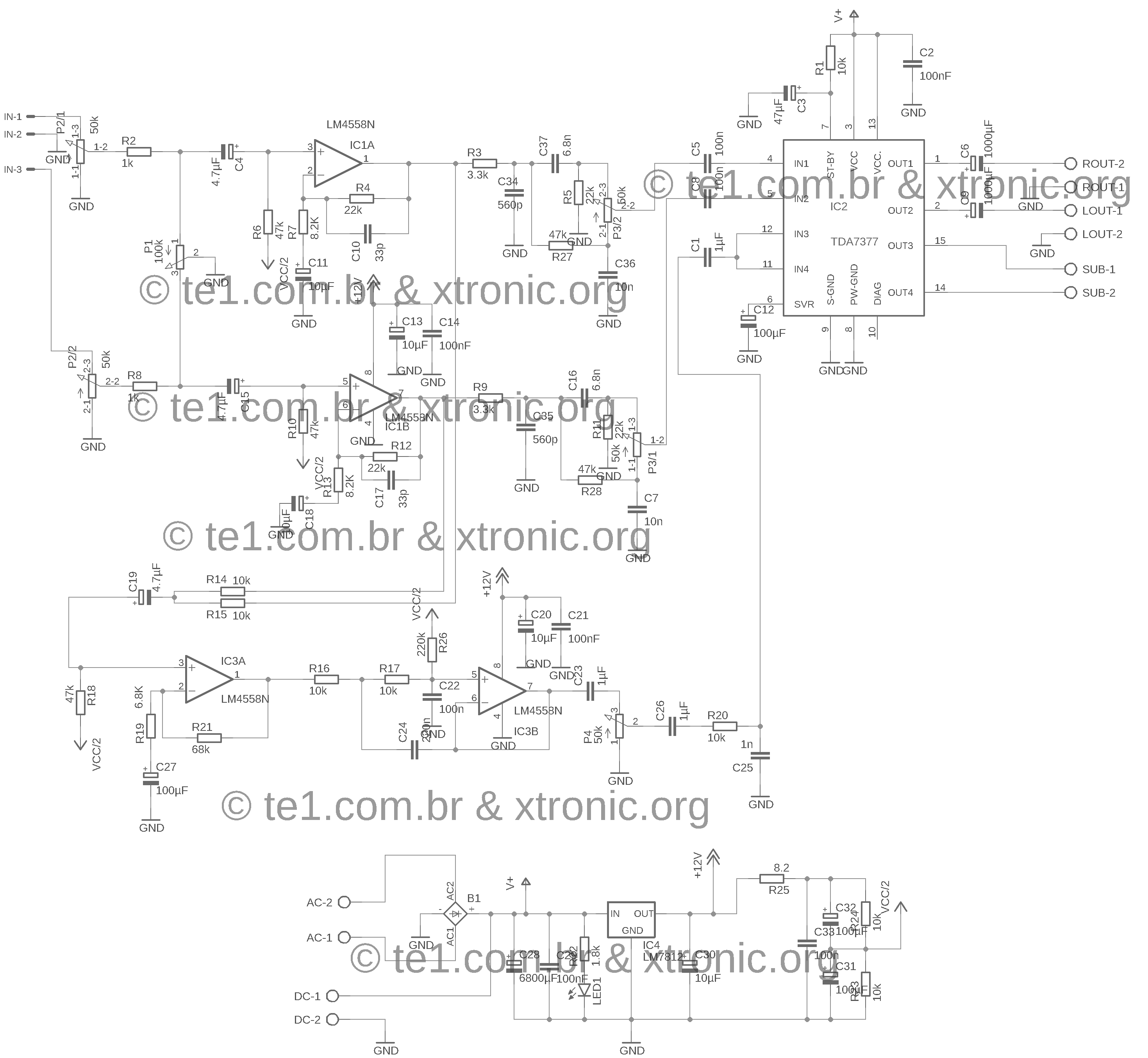
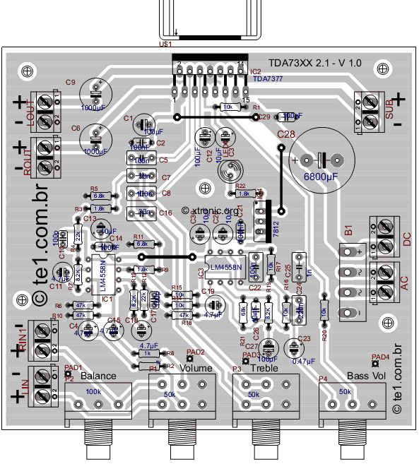
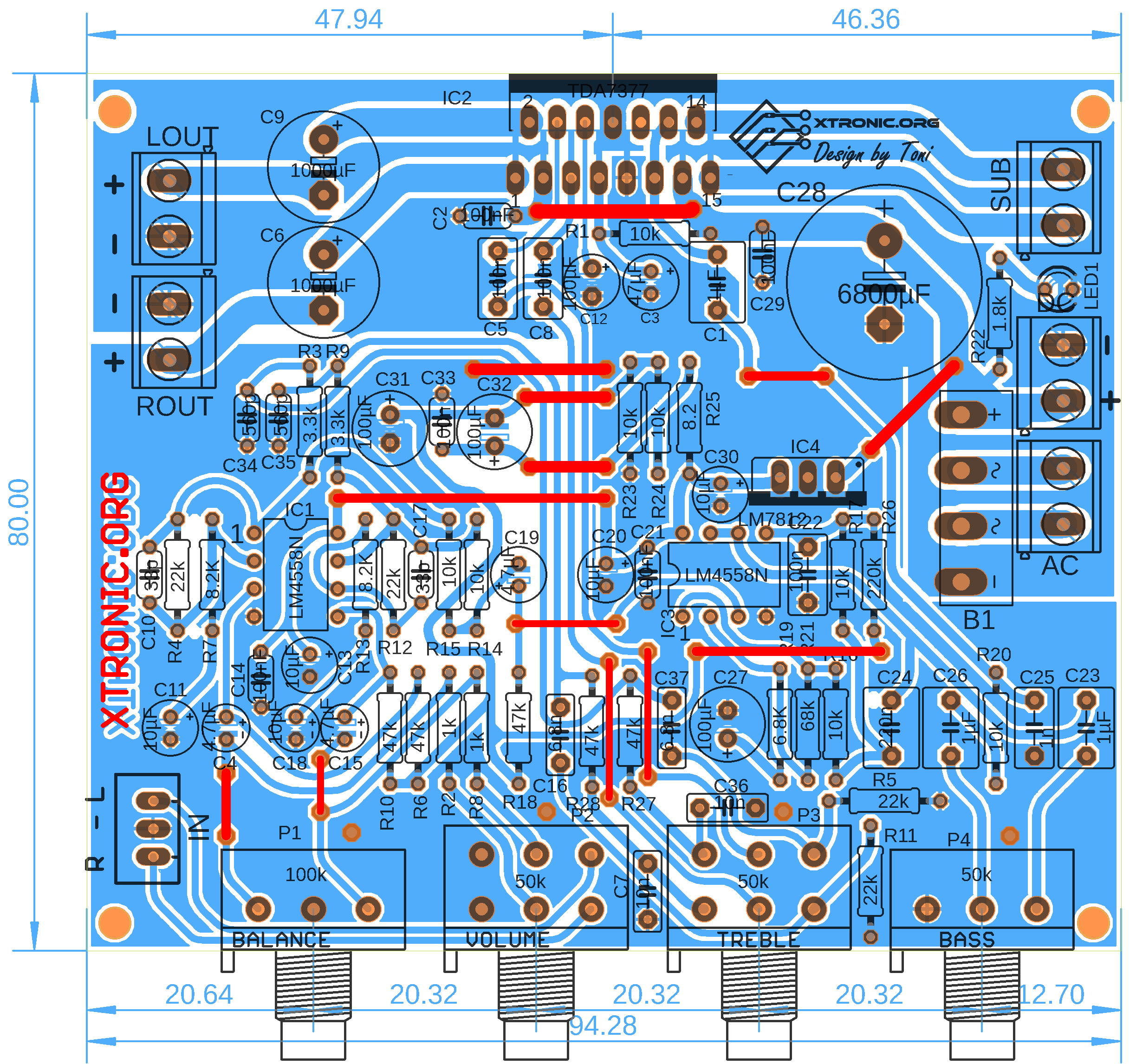
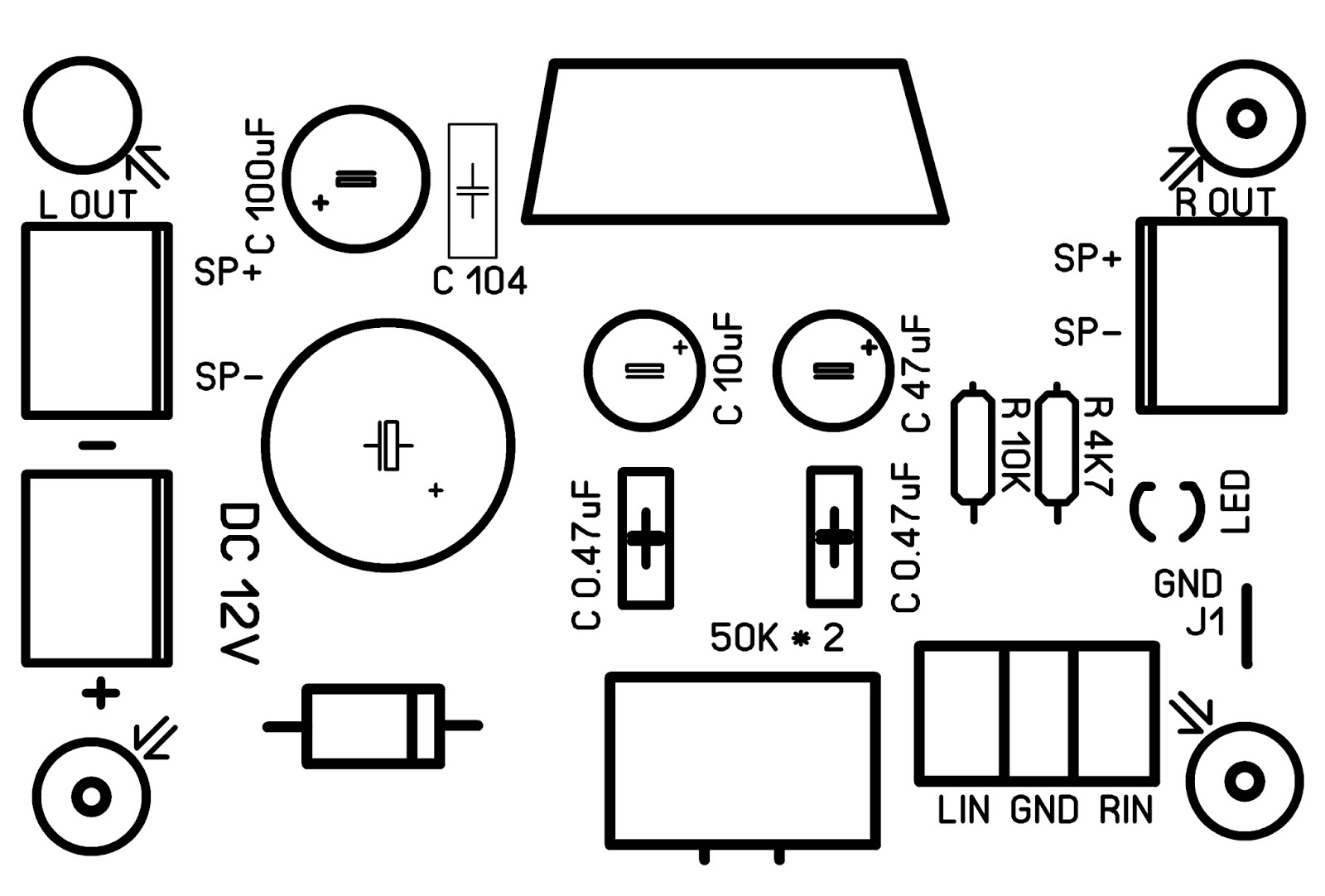
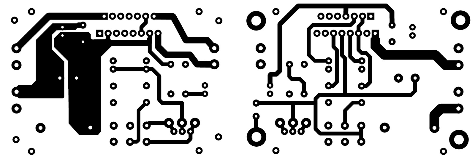
Schematic TDA7377 2.1 amplifier circuit diagram with PCB - Stereo + Subwoofer Suggested PCB design for TDA7377 2.1 amplifier circuit diagram BOM for assembling the circuit tda7377 2.1 amplifier
TDA7377 2x30W Dual/Quad Power Amplifier
Here's the overall schematic of this TDA7377/ TDA7379 2.1 amplifier: The following is the layout design of the 2.1 TDA7377 TDA7379 amplifier which was drawn by Barlex Respectaizer: The next step is to print the PCB on PCBWay, using the gerber file, this Amplifier gerber file can be downloaded at the end of the post.

Tda7377 Amplifier Circuit Diagram
Small amplifier TDA7377 of 15W + 15W + 30W in 4 ohms At the request of our followers, we have developed an amplifier with the following characteristics: The TDA7377 is the main component. It has 4 outputs that can deliver a power of 15W each. we distribute them as follows: First, we have 2 outputs of 15W, which form a stereo amplifier.

Amplifier stereo suara bening, cara membuat amplifier menggunakan IC
The TDA7375AV is a technology class AB car radio amplifier able to work either in dual bridge or quad single ended configuration. The exclusive fully complementary structure of the output stage and the internally fixed gain guarantee the highest possible power performances with extremely reduced component count.
